Start with your own hands. Connect a value to the screen, make a button work, and test it. Then let AI help with the finishing touches — all without writing code.
EVK043027B · 480 × 27210 short stepsNo external controller needed
You already have the desktop app installed. Open it now. Keep the AI Assistant closed until step 7; your configured key will be used there.
This guide uses the EVK043027B and its built-in brightness example. Have its normal power supply and programming connection ready for step 9. You can complete the editing and Preview steps without a connected board.
Using another 480 × 272 board? Its screen may match, but this example controls the EVK's dimmable backlight. Use EVK043027B for this exact exercise; a generic value on another board does not demonstrate physical dimming.
The guide offers the same five languages as the product page, using Google's online translation. App labels, names and example values below stay in English so you can find them in the desktop app. This page's language menu does not change the HMI project's language.
01Home → Examples
Make a project of your own
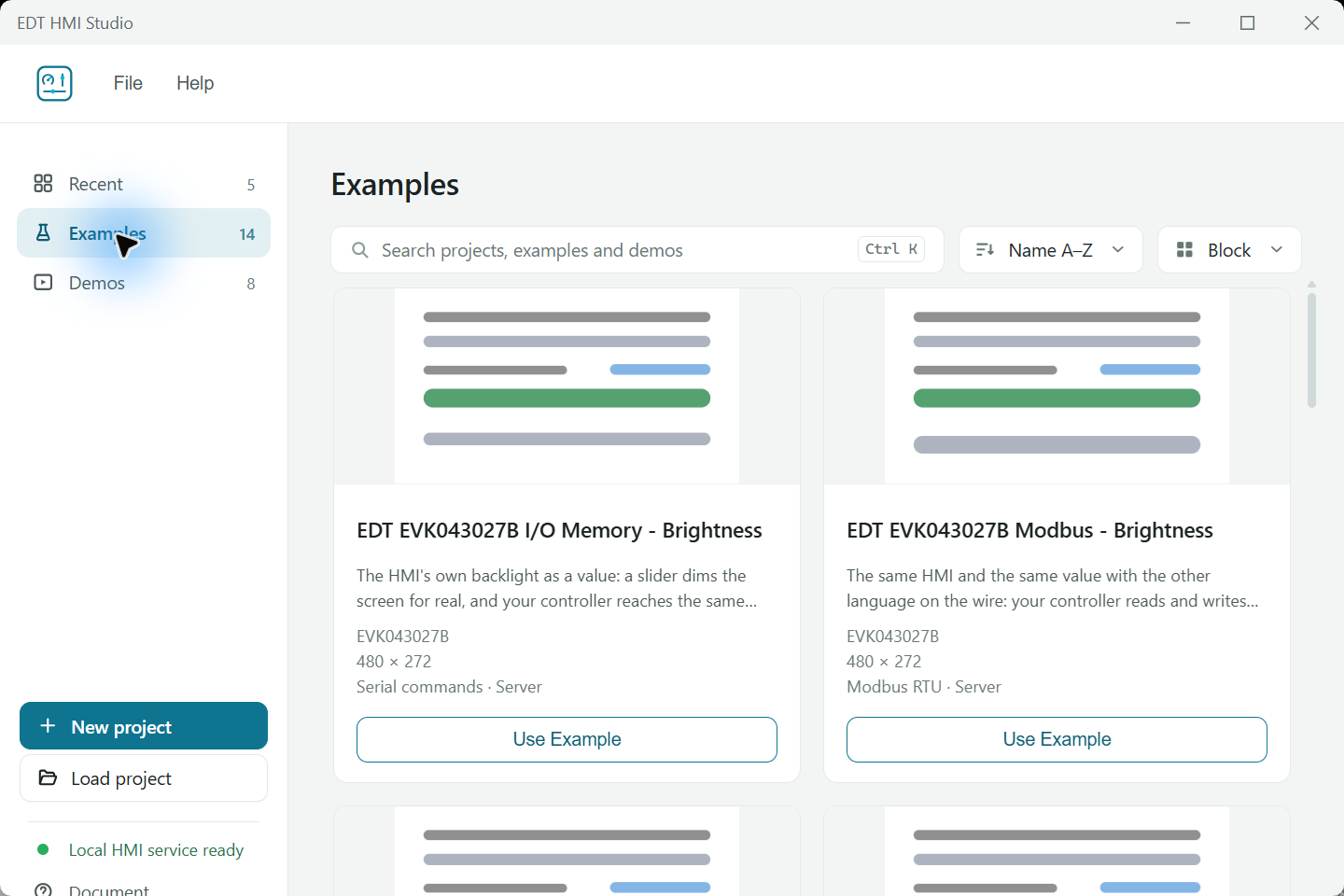
Open Examples. Find EDT EVK043027B I/O Memory - Brightness.
Press Use Example. Enter My Brightness Panel, choose your Project Folder, and press Create.
The Design workspace opens. Locate the canvas in the middle, Components and Hierarchy on the left, and Properties on the right.
Check: You have a 480 × 272 screen called Brightness with a slider and a numeric readout. Your copy is an .ehsp file; the example stays available.
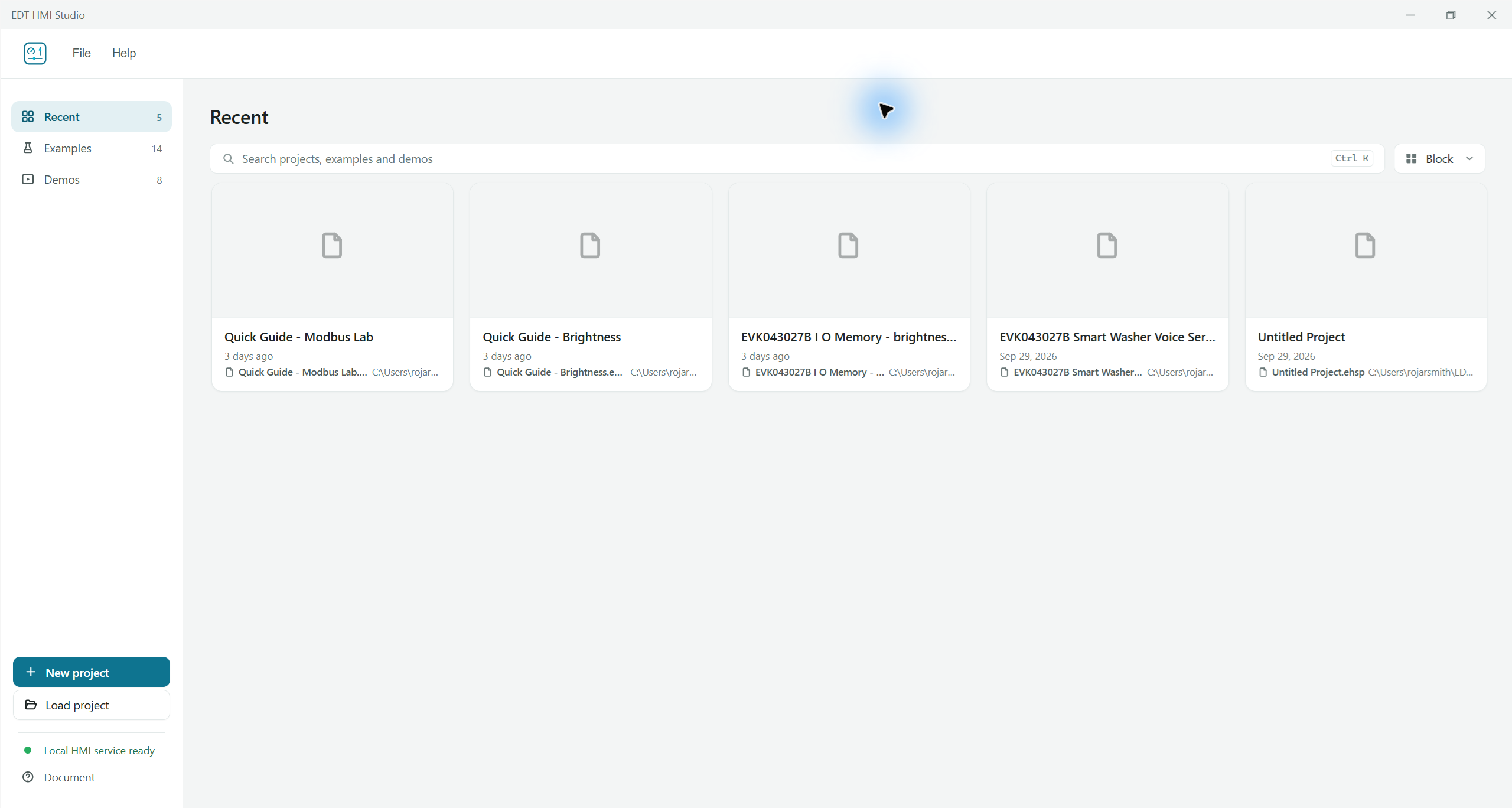
Choose the I/O Memory example on the left. Click any screenshot to inspect its original pixels. The stylized thumbnails are shown by the installed desktop version.Starting from the project manager?The installed desktop app's project manager, captured again at native resolution. Open Examples to begin.
02Asset → Text → Texts
Make the words yours
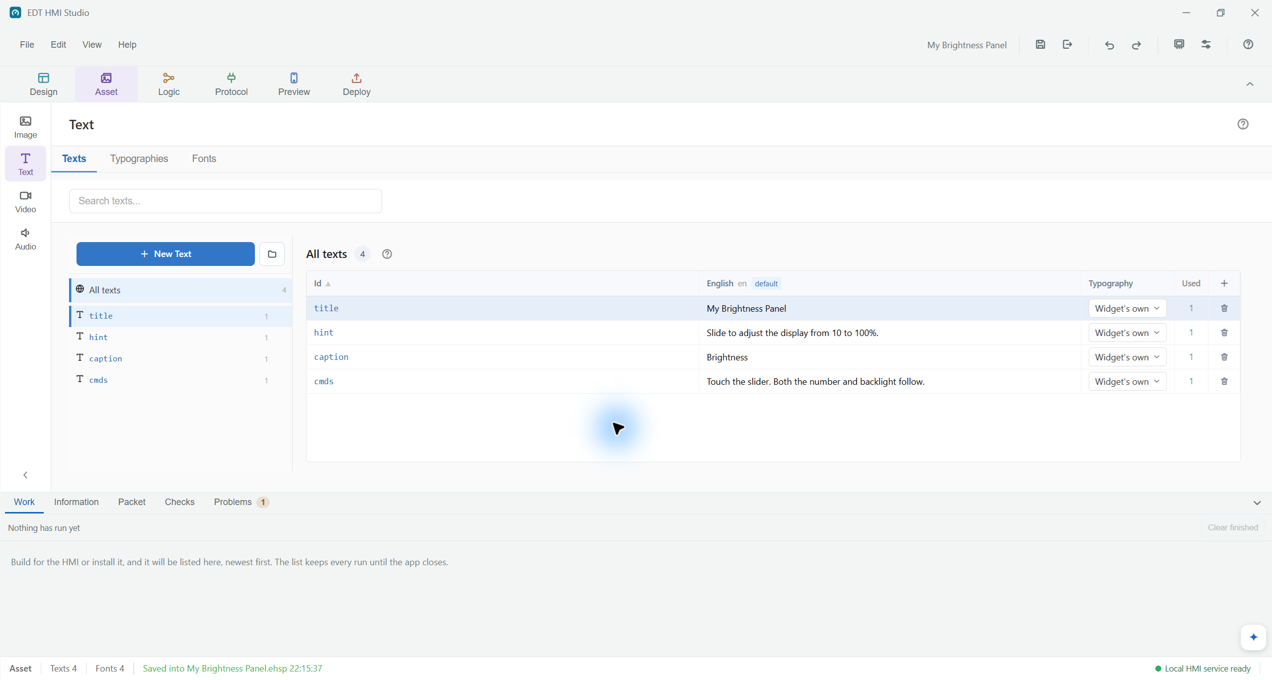
Open Asset → Text → Texts. Edit the English cells below, then click outside the cell to commit.
Text ID
Enter these words
title
My Brightness Panel
hint
Slide to adjust the display from 10 to 100%.
caption
Brightness
cmds
Touch the slider. Both the number and backlight follow.
Return to Design to see the changes. A widget points to a shared text resource: editing that row updates every widget using it. Use Typographies to control font and size.
Check: The title reads My Brightness Panel. The long technical instructions have become a short hint.
Texts hold the words; typographies hold the font settings.Optional: give the HMI a second language
Use the + at the right of the text-table header to add a language column and fill its translations. For Chinese, Japanese or Korean, choose the corresponding bundled Noto font under Typographies. Select that typography for the text. A font without those characters cannot display them. This is separate from Google's translation of this guide.
03Design → Components / Properties
Add one useful control
Search Components for Button and drag it onto the bottom of the canvas.
Select the new button. Keep its ID Button_1 and set Text to Reset 100%.
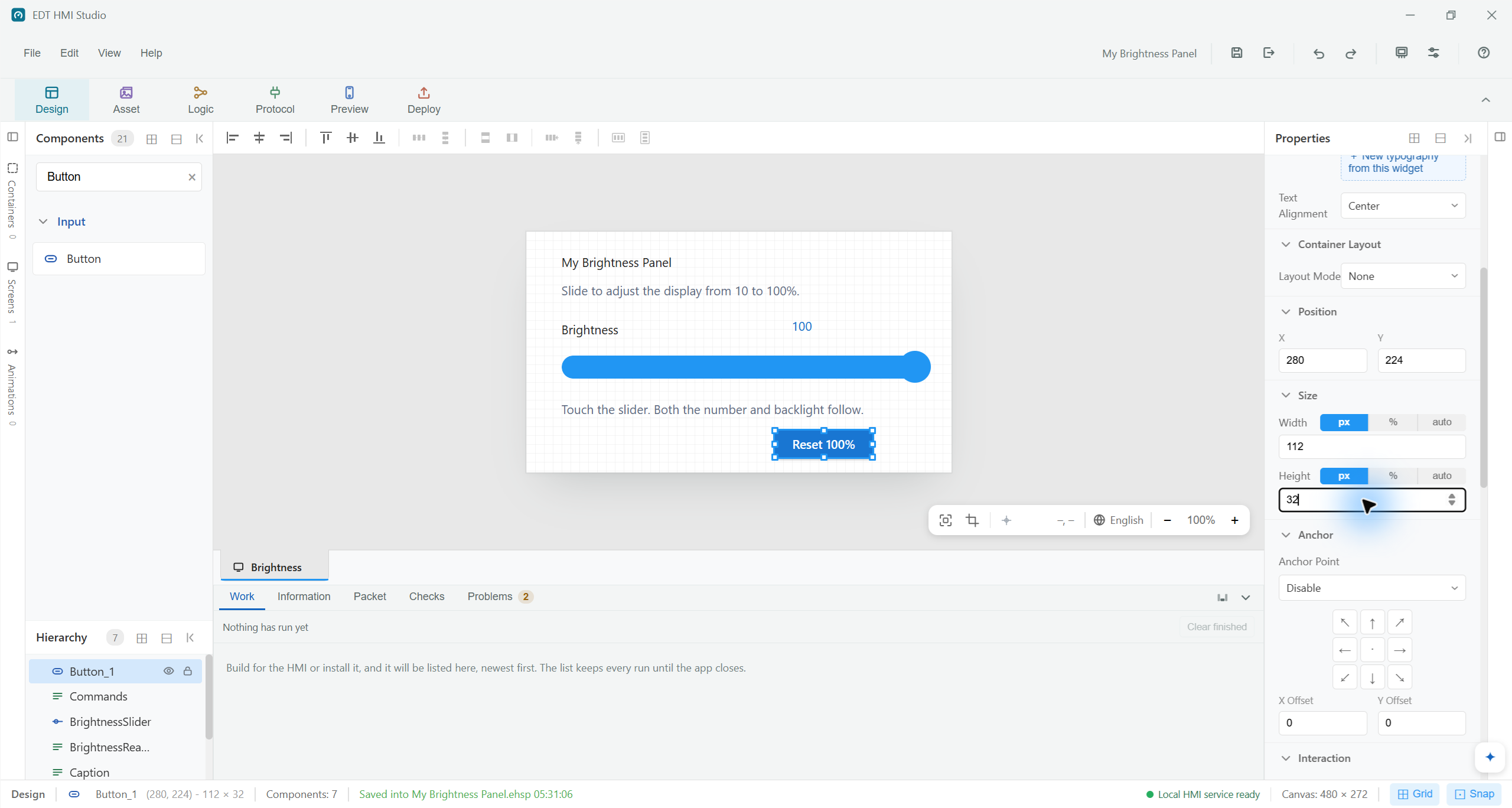
Under Position and Size, set X 280 · Y 224 · Width 112 · Height 32 in pixels. The Hierarchy helps you select a widget when items overlap.
Check: The button fits below the footer and inside the screen. It will get its action in step 5.
Use exact position and size values when a quick drag needs fine adjustment.
04Protocol → I/O Memory · Design → Bindings
Follow one value through the screen
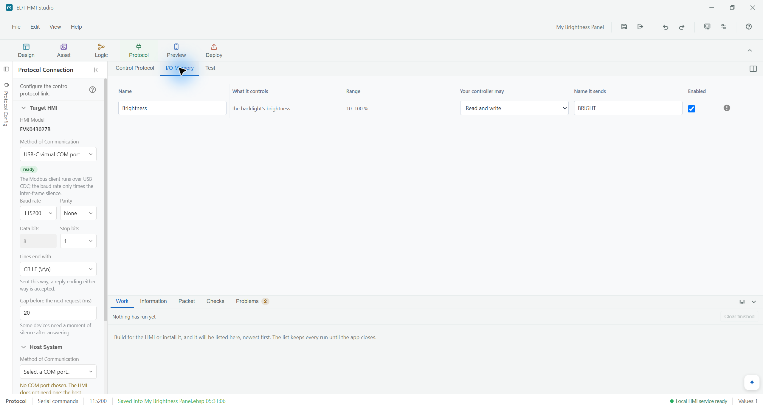
Open Protocol → I/O Memory. Find Brightness, range 10–100%, and leave Enabled checked. The example already gives it the command name BRIGHT.
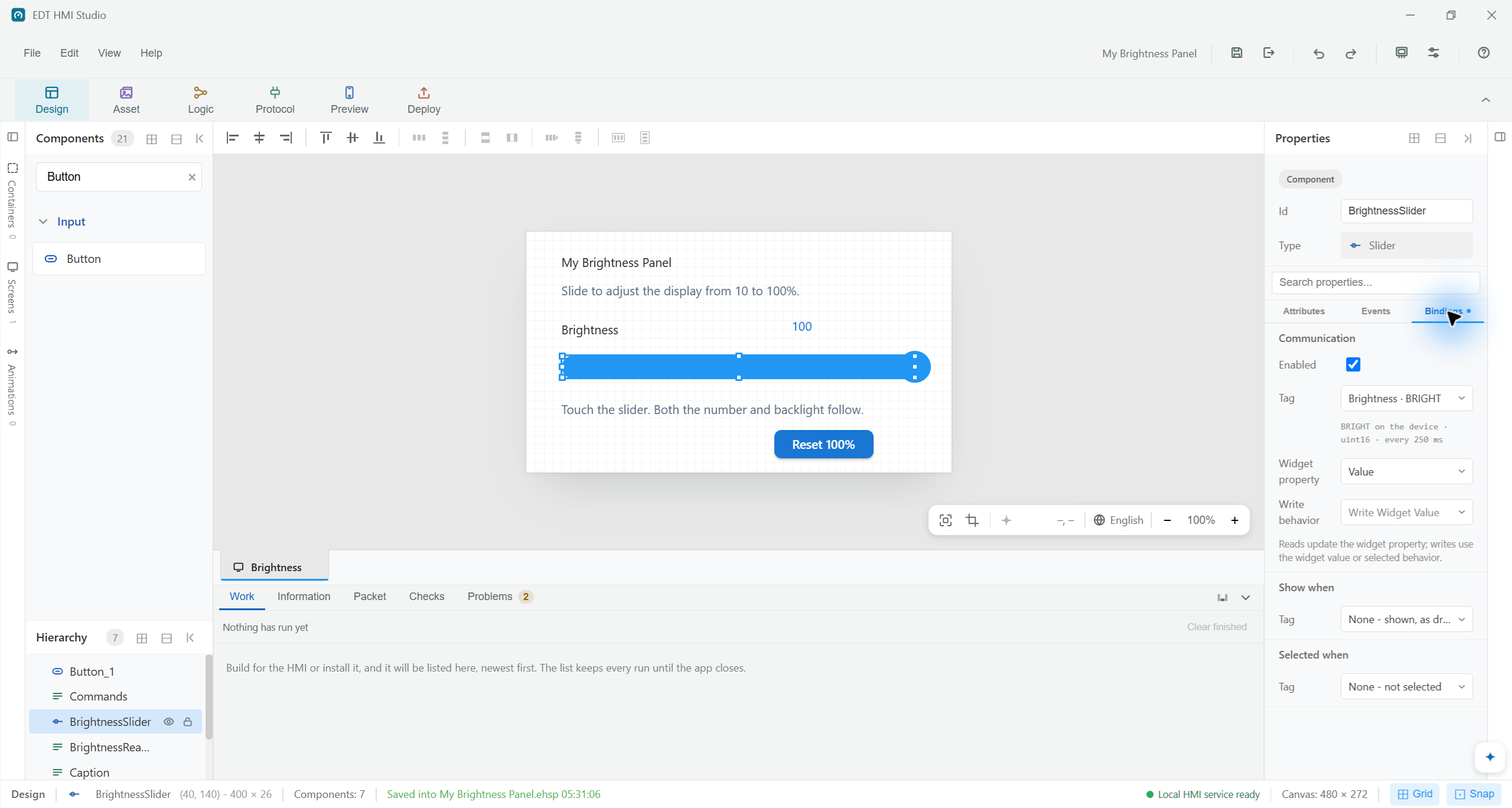
In Design, select BrightnessSlider and open Bindings. Confirm communication is enabled, the tag is Brightness, the widget property is Value, and the write behavior is Write Widget Value.
Select BrightnessReadout and inspect its binding to the same tag. The slider changes the value; the label displays it. On the EVK, that value also controls the backlight.
Check: One named value connects the slider, the number and the hardware. You did not create a second value for the label.
The board's own brightness lives in I/O Memory. No external controller is needed to move it with the slider.See the slider's Bindings panel
05Design → Properties → Events
Make the reset button respond
Select Button_1. Open Events and press +.
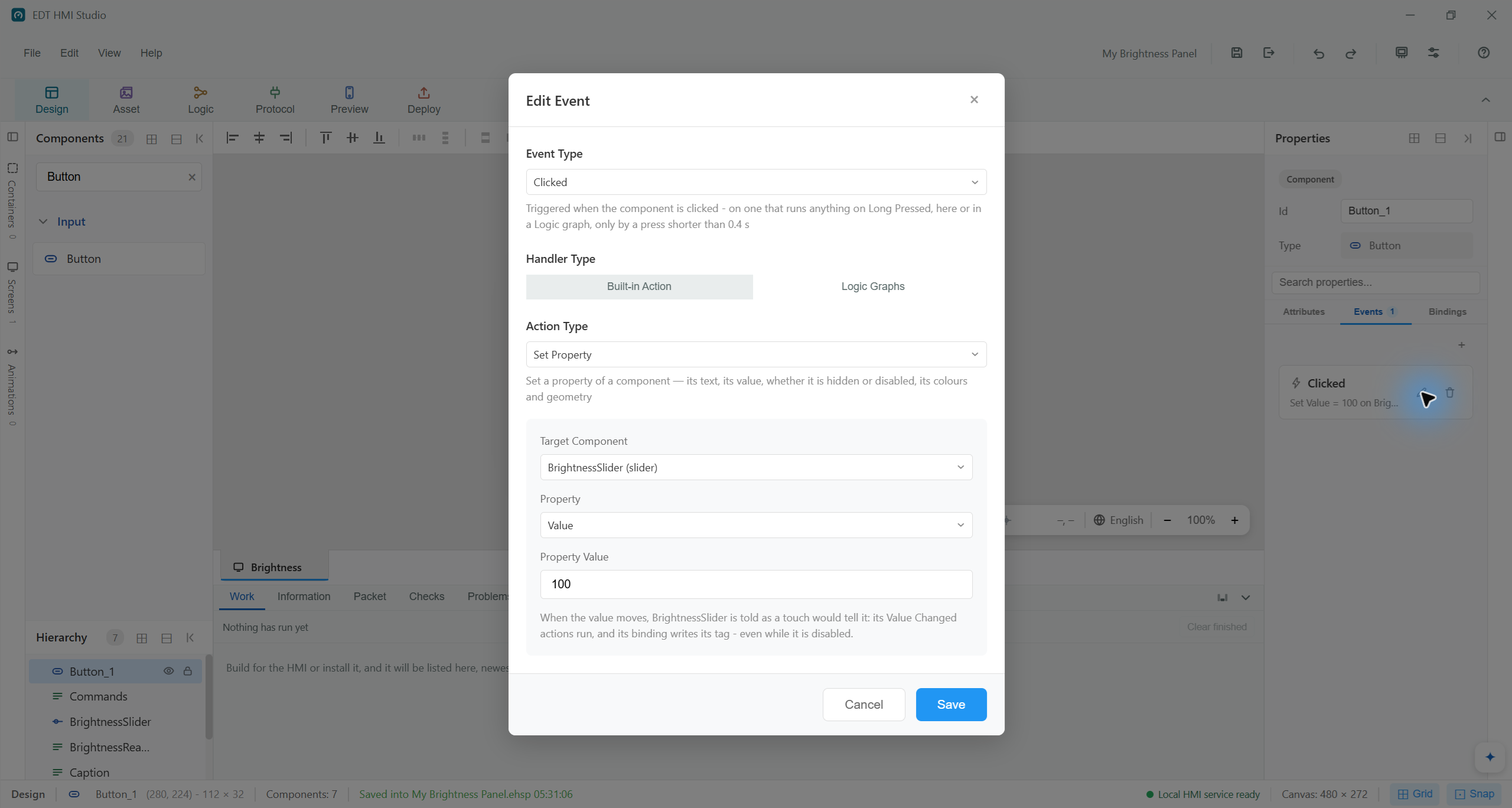
Choose Clicked → Built-in Action → Set Property. Set Target Component to BrightnessSlider, Property to Value, and Property Value to 100.
Press Save, then save the project with Ctrl+S.
Check: The Events panel shows a Clicked action that sets the slider to 100. The slider's binding sends that value to Brightness.
An event answers “when”; the action answers “what happens”.Optional extension: do the same job with Logic
For a sequence of actions, use a graph. In Logic, press + in Graphs and name it ResetBrightness. Drag in an Event Trigger and a Set Value node. Set the latter's target to BrightnessSlider and its Number input to 100. Connect the trigger's Execute output to the action's Execute input.
Return to the button's existing Clicked event. Change its handler to Logic Graphs, check ResetBrightness, and save. Keep the graph active. Test the same reset again. This replaces the built-in action; there is no need for two reset handlers.
The main walkthrough uses the simpler built-in event. This optional graph extension is not shown in the video.
06Preview → Start
Test before you connect the board
Open Preview and press Start. The first preparation may take a few minutes.
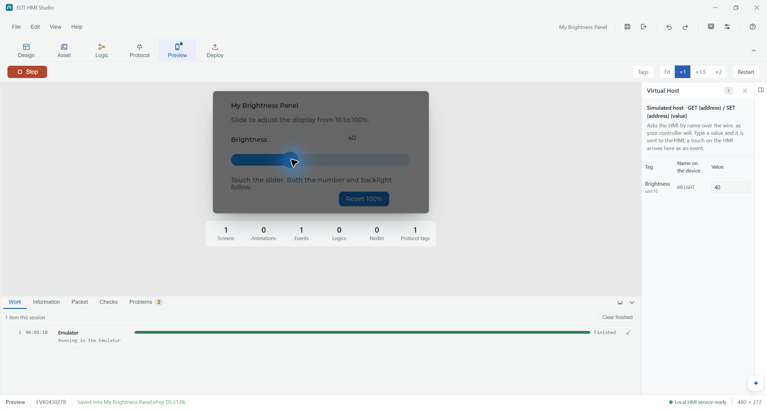
Drag the slider down to about 40. Check that the number changes and the preview dims. The Virtual Host value follows too.
Press Reset 100%. The number returns to 100 and the screen brightens. Try both ends of the slider: the minimum is 10, not zero. Press Stop before editing again.
Check: You now have a working panel made entirely by hand. Save it before starting the AI section; use File → Save As… if you want a separate pre-AI version.
Observed in the desktop app: slider, readout and simulated brightness agree at 40.
07AI Assistant · First AI step
Ask AI for a small, precise improvement
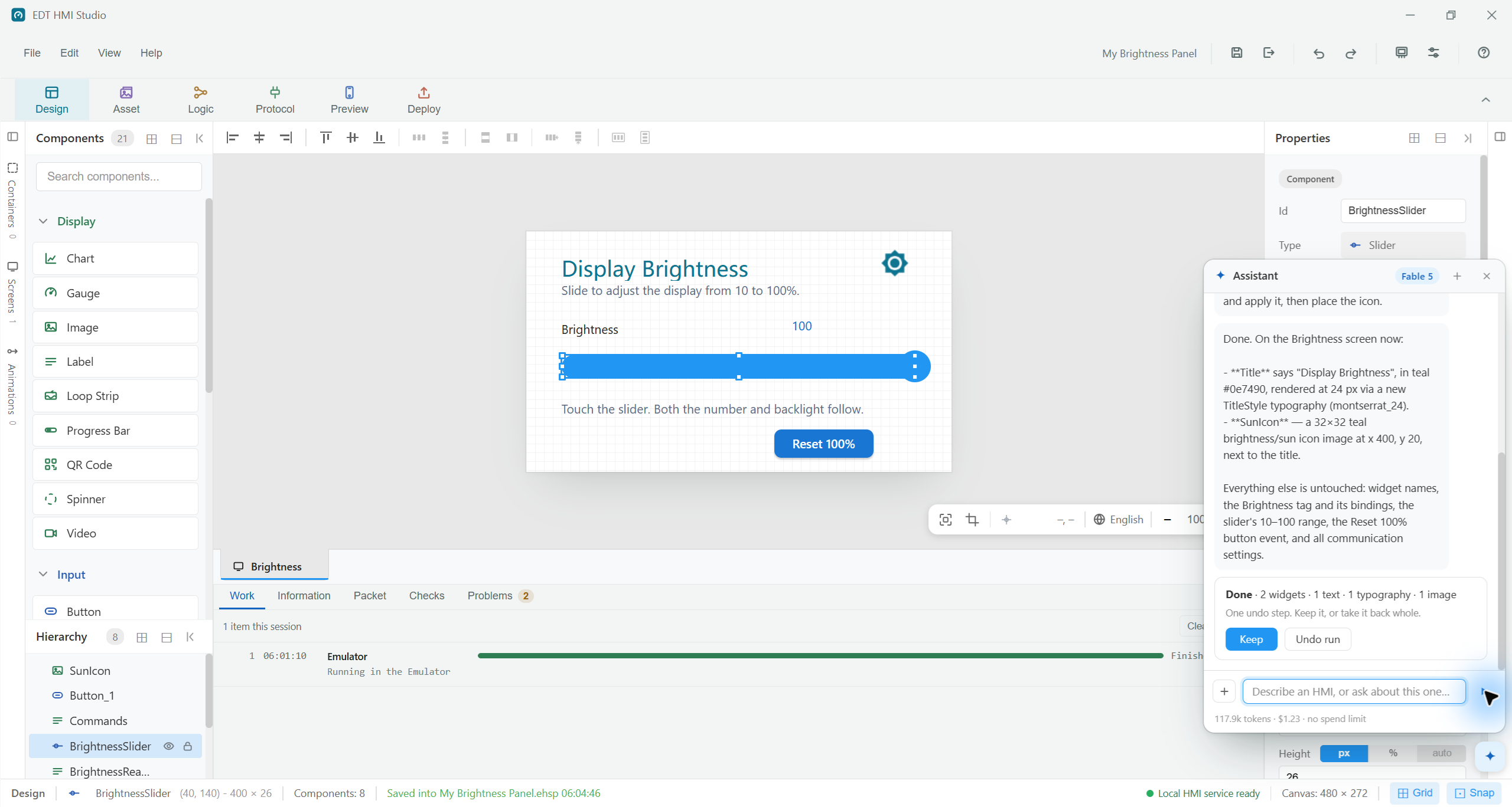
Return to Design and open the floating Assistant button. Your key is already configured. Paste this request and press Send; you can also ask in your own language.
Polish only the Brightness screen: change the Title text to "Display Brightness", make its text teal (#0e7490) and 24 px, and draw a small sun icon at x=400, y=20, size 32x32. Keep all widget names, the Brightness tag, bindings, slider range and Reset 100% button event unchanged. Do not change hardware, logic graphs or protocol settings.
The request says what to change and what to preserve. AI can edit shared texts, typography, widgets and image assets. It uses the configured provider; the run's usage appears in the Assistant.
Check: Wait for the run to finish. The title and sun icon should appear as normal editable project content.
This actual run added a typography and sun image and updated the shared title. Your model's details may differ.
08Review → Design → Preview
Review it as the designer
Read the Assistant's change summary. Choose Keep if the result fits, or Undo run to take the whole run back.
Close the Assistant. Select Title and the new icon in Hierarchy. Inspect their position, typography and size. If the title's box reaches under the icon, reduce its width to 350 in Properties.
Start Preview again. Repeat the slider and reset test from step 6. Check that the icon and larger title fit. Save the reviewed result.
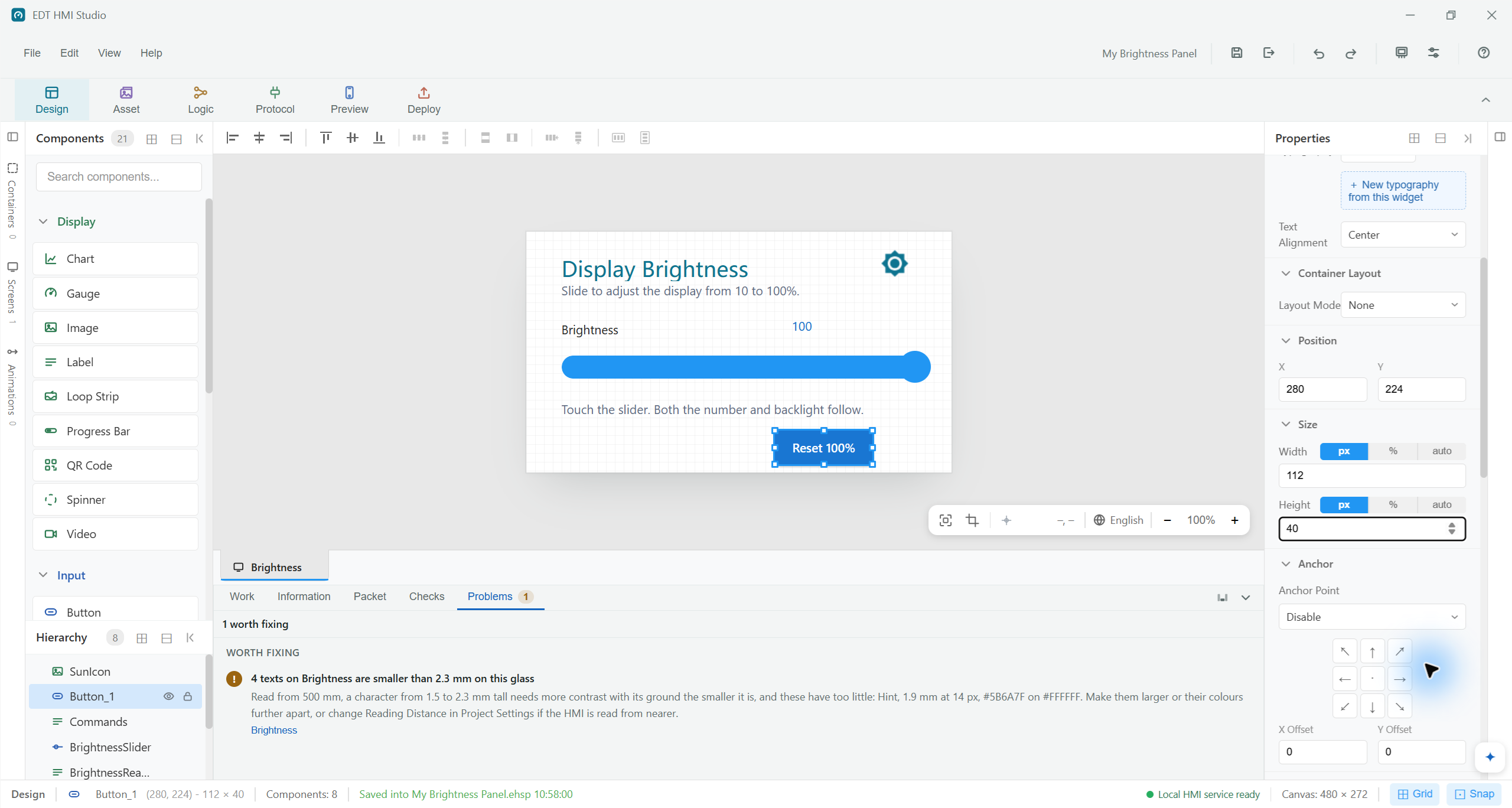
Open Problems to review the design too. Follow the small touch-target warning to Button_1 and increase its Height from 32 to 40. Keep Y at 224: its bottom is still inside the 272 px screen. Review small-text and contrast warnings before using the panel on hardware.
Review includes usability: make the reset button easier to touch.
Check: The panel looks better and still behaves the same. AI changes stay editable by hand. Deployment remains your action.
A useful follow-up question: Explain how BrightnessSlider, BrightnessReadout and Button_1 work together. Do not change anything. The Assistant can explain existing logic; this guide does not rely on AI authoring Logic graphs.
09Deploy → HMI
Put the reviewed panel on the display
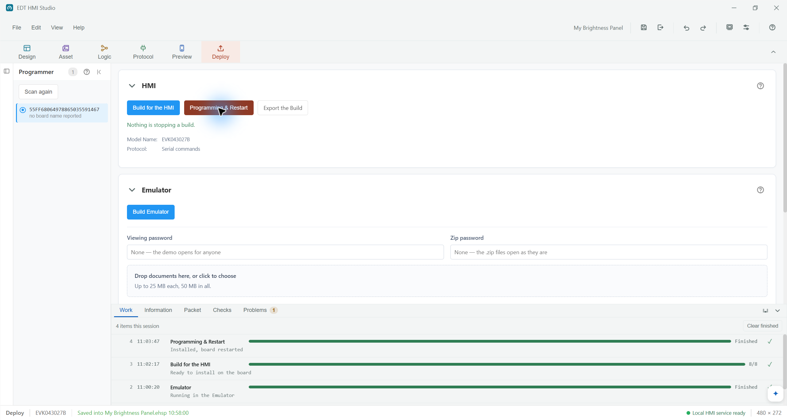
Power your EVK043027B and connect its programmer. In Deploy, confirm Model Name: EVK043027B. Use Scan again and select the intended programmer on the left.
Press Build for the HMI. Follow progress in Work. If anything blocks the build, open Problems and follow the reported item to its setting.
Once the build succeeds and the intended board is connected, press Programming & Restart. On the physical display, slide to 40 and press Reset. The real backlight should dim and recover.
Check: The HMI starts with the reviewed screen. Its touch controls work without the PC's Preview running.
The programming connection and the Protocol host COM port have different jobs. This local brightness exercise needs no external controller. To try GET BRIGHT or SET BRIGHT 40 later, first install the project, then use the EVK's USB-C virtual COM connection with the example's 115200, 8N1 and CR LF settings.
The reviewed project was built and programmed successfully. The protocol lab below verifies replies from the connected EVK; no camera recording of the physical display is included.
10Deploy → Emulator · File → Save Project
Share the result, keep the editable project
On Deploy, press Build Emulator. When it is ready, choose Save for a PC (.zip).
Extract the ZIP and open HMI Demo.html, or use Run HMI Demo.cmd on Windows. Try the slider and reset again. A colleague can run the demo without the Studio or a board.
Save your .ehsp project with Ctrl+S. Keep that file for future editing. Rebuild the emulator whenever you change the project.
Done: You have an editable project, a working screen, and a path to both a real HMI and a shareable demo.
LabSerial Debug Assistant · mbtools
Let a PC control the same value
After step 9, try the two protocols below one at a time. The PC sends a request and the EVK answers. Start with the text protocol already in your brightness project; try Modbus in a separate example copy.
Two separate connections: Protocol commands use the EVK's USB-C virtual COM port (COM12 in this session). Putting your HMI on the board uses the programmer selected in Deploy. Do not choose the programmer's serial port for protocol testing. COM numbers vary between PCs. Close the protocol port in the other tool and stop any Studio connection using it before opening it here.
A · Serial Debug Assistant: readable commands
Run the installed Serial Debug Assistant + TCP/UDP. Choose the EVK's Port Name, 115200, 8 data bits, None parity and 1 stop bit. Leave flow control off.
Turn off HEX send and HEX display. Set the send line ending to CR LF (bytes 0D 0A), then press Open.
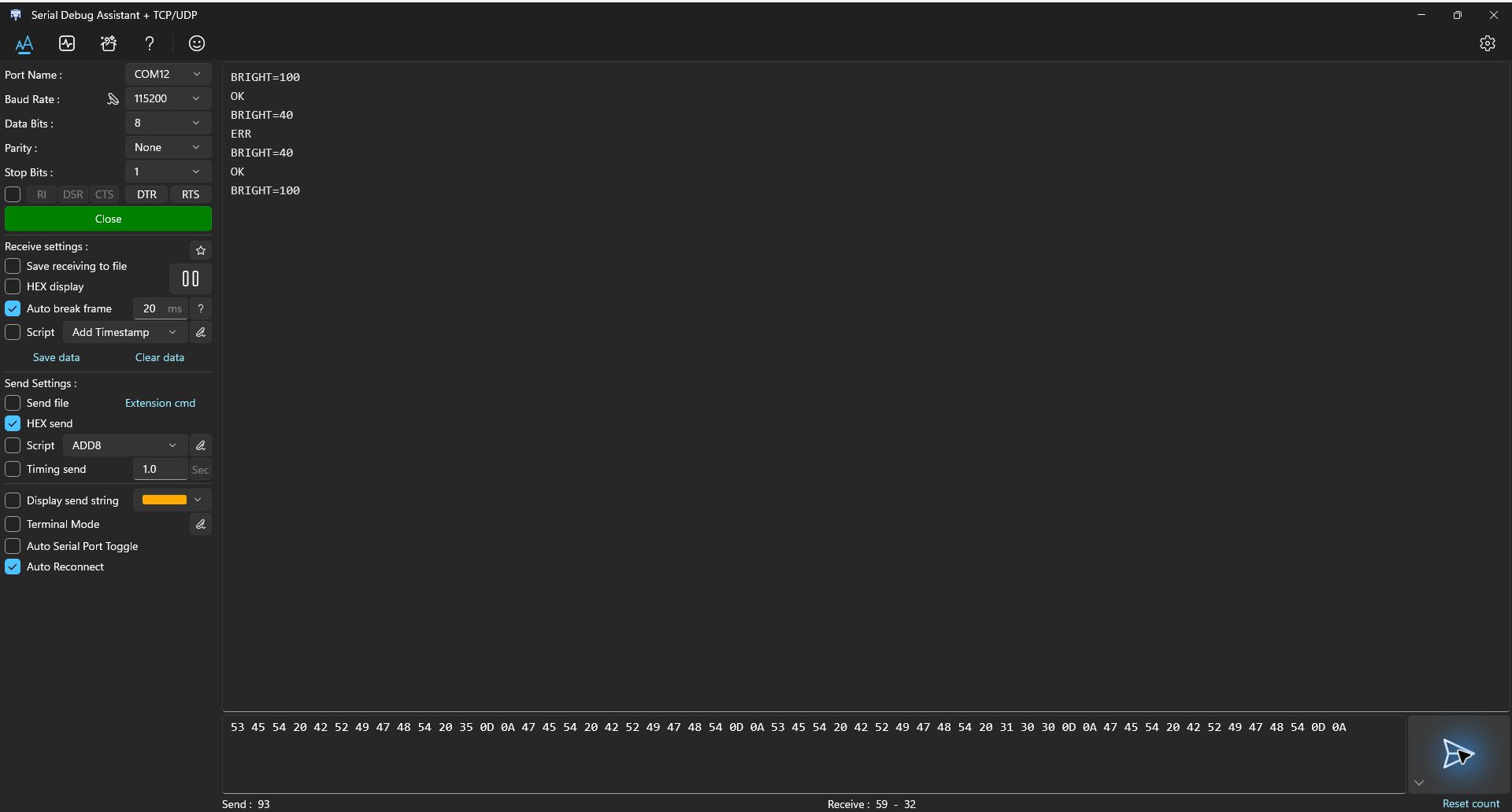
Send each line below separately. Check the reply and the HMI's number after each write. Finish at 100, then move the slider on the HMI and read again.
Send (with CR LF)
Expected reply
Check on the HMI
GET BRIGHT
BRIGHT=100 if currently 100
Read the current value
SET BRIGHT 40
OK
40, screen dims
GET BRIGHT
BRIGHT=40
Read-back agrees
SET BRIGHT 5
ERR
Stays at 40: minimum is 10
SET BRIGHT 100
OK
100, brightness restored
No CR LF option? Use the exact bytes from this demonstration
Keep HEX display off and enable HEX send. Paste one row below, then press the send arrow. Each row already ends with 0D 0A; keep Script and Timing send off.
Command
HEX send
GET BRIGHT
47 45 54 20 42 52 49 47 48 54 0D 0A
SET BRIGHT 40
53 45 54 20 42 52 49 47 48 54 20 34 30 0D 0A
SET BRIGHT 5
53 45 54 20 42 52 49 47 48 54 20 35 0D 0A
SET BRIGHT 100
53 45 54 20 42 52 49 47 48 54 20 31 30 30 0D 0A
Verified on the connected EVK: write 40, read 40, reject 5, keep 40, restore 100. The capture uses HEX send to include CR LF explicitly; replies remain readable text.
B · mbtools: read and write a Modbus register
Save the text-protocol project and close its serial port. From Studio's Examples, create a separate copy of EDT EVK043027B Modbus - Brightness. In Protocol, inspect the Modbus RTU connection and I/O Memory. Build and program this copy before sending Modbus requests.
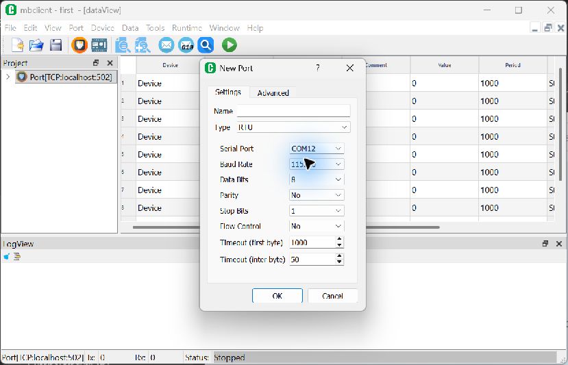
Run mbclient.exe from your installed mbtools folder. Double-click the existing Port to edit it (or choose New Port if none exists). Set Type: RTU, the EVK's protocol COM port, and 115200 / 8 / No parity / 1 stop bit / No flow control. Press OK.
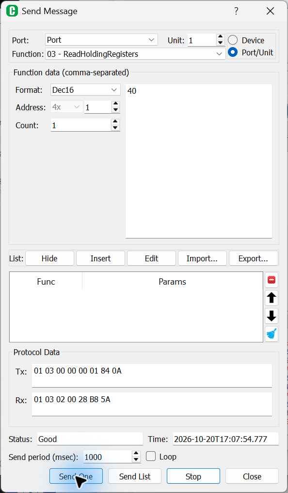
Open Send Message. Choose Port/Unit, select that port, and set Unit to 1. Choose 03 - ReadHoldingRegisters, format Dec16, address 4x · 1 and count 1. Leave Loop off and press Send One. The result should be 100 with status Good.
Change the function to 06 - WriteSingleRegister. Keep address 4x · 1, enter Value40, and press Send One. Switch back to function 03 and send again: the read-back should be 40. Compare it with the physical display.
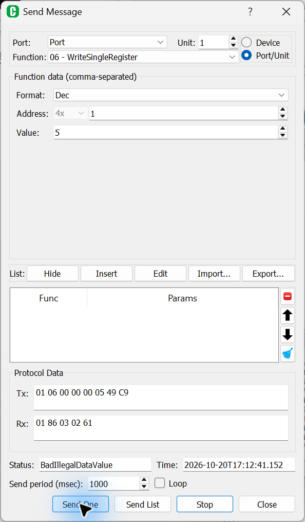
Repeat function 06 with value 5. Expect BadIllegalDataValue (exception 03); function 03 should still read 40. Write 100 and read it back to finish. Close Send Message, then press the main toolbar's Stop button to stop polling and release the port.
Address trap: In this Send Message window, use 4x with address 1. This is holding register 400001, or raw zero-based address 0. Only enter 0 in a tool explicitly asking for a raw address. Use mbclient.exe here because the PC asks and the HMI answers. mbserver.exe is for examples where the HMI is the Modbus master.
Use RTU for this USB serial example. The default TCP localhost port in the background is not this board connection.
Actual FC03 read-back: 40, status Good.Actual FC06 boundary check: 5 is rejected.
If mbclient opens its sample data view with ten registers, background polling may report exception 02: that sample requests addresses this brightness example does not expose. Use the single-register settings above and inspect the status inside Send Message. For a polling dashboard, configure only register 400001 with count 1.
No reply? Check these four things
The flashed project uses the same protocol as the tool. Text commands and Modbus RTU cannot be swapped without changing the project.
The correct board's COM port is open in only one application.
Text commands end with CR LF; Modbus uses unit 1 and holding-register offset 0.
A successful write is followed by a successful read-back and a matching screen value. A sent-byte counter alone does not prove communication.
Verified on EVK043027B: Both tools completed read 100 → write/read 40 → reject 5 → read unchanged 40 → restore/read 100. The screenshots and video include the actual received replies. When demonstrating in person, also show the physical display beside the PC.
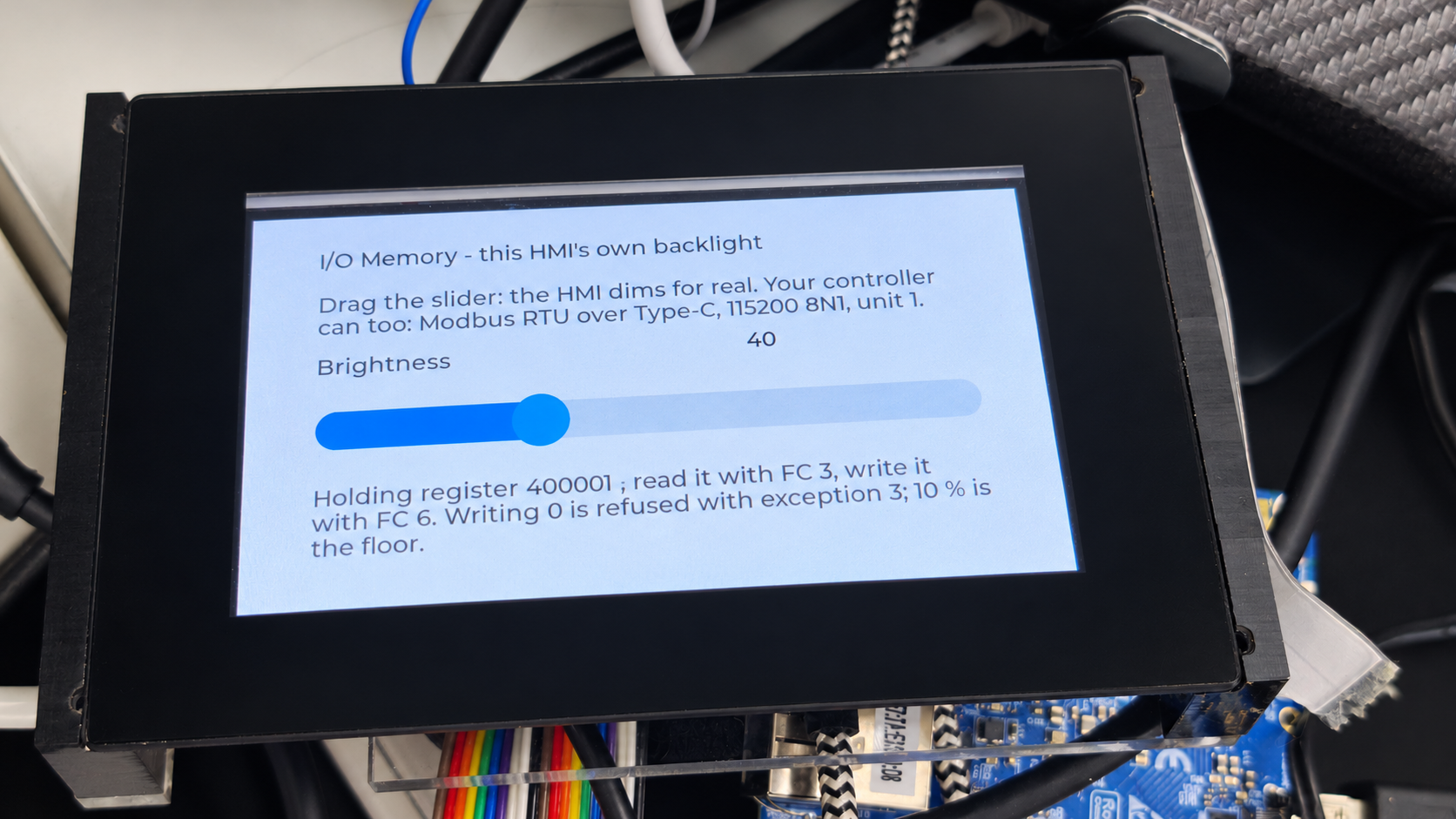
The supplied EVK043027B photo at 40, with AI-assisted glare removal for reference. View the unedited original. The retouched image is illustrative; protocol evidence comes from the actual receive captures above.Follow the actual desktop session
Watch the steps
A 1440p walkthrough with readable instructions, full-window views and enlarged details from the real desktop captures. The final scene pairs the Modbus result with the retouched board photo. Pause whenever you want to follow along.
For small UI text, use original pixel size or download the video. The inline player fits your page width. This is an edited screenshot walkthrough. EHS images and the featured Modbus replies were recaptured at native resolution; remaining earlier protocol captures retain their original compression.
Download MP4 · English captions. Screenshots and video show the English desktop UI; use the language menu for the guide text.
What you just learned
Design gives a value a useful shape. Assets keep words and artwork reusable. Bindings connect the screen to data. Events and Logic turn interaction into behavior. Preview lets you test, AI helps refine, and Deploy takes your reviewed work to the display.